简体中文 

5F,W2,Chengxin Building,Tian A an An Shen Chuang Valley Industrial Center,Fenggang Town,Dongguan City,中国广东省523681


产品描述

The size

The pins definition

Reference design
1、 网口与网络变压器之间需要严格按照差分信号走线。


2、 T1需要选择支持POE++的 10G 的网络变压器。
3、 网口与网络变压器之间需要严格按照差分信号走线。
4、 J2是PSE输出端口,J1是网络输入端口
5、 PR12,PR45接VMAIN-54V;PR36接PSE1-A;PR78接PSE1-B
6、 Bobsmith电路需要保留,EARTH对接PSE模块的FGND
7、 电源主板需要2路输出,54V-56V与5V-12V;因为PSE模块支持IEEE802.3bt协议,大支持class8,建议54-56V功率大于90W。
8、
电源主板54V-56V 对接PSE模块的VMAIN-54V
电源主板5V-12V 对接PSE模块的5-12V输入
电源主板DC地 对接PSE模块的GND
电源主板输入AC的 PE地 对接PSE模块的FGND
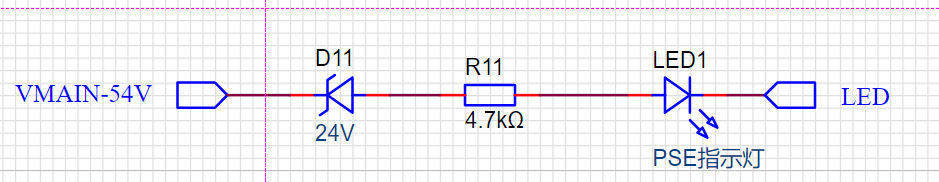
电源主板 54-56V串24V稳压管串4.7K电阻串LED灯 对接PSE模块的LED

当PSE对外供电时,LED1点亮
Reference design Translation
1. T1 needs to select a 10G network transformer that supports POE++
2. The RJ45 and the Network filter must be layout in strict accordance with the differential signal
3. J2 is the PSE output port and J1 is the network input port
4. PR12,PR45 connect to VMAIN-54VPR36 connect to PSE1-A;PR78 connect to PSE1-B
5. Bobsmith circuit needs to be retained, EARTH connects to the FGND of PSE module
6. power motherboard needs 2 port output, 54V-56V and 5V-12V; Because the PSE module supports IEEE802.3bt and class8. It is recommended that the power of the PSE module be 54-56V and bigger than 90W
7. Power board 54V-56V connnect to PSE module VMAIN-54V
Power board 5V-12V connect to PSE module 5-12Vinput
Power board DC GND connect to PSE module GND
Power board input AC’’s PE GND connect to PSE FGND
Power board 54-56V connect to 24V Voltage regulator tube then connect to 4.7K resistance then connect to LED then to PSE module’s LED
When PSE supply power ourisde .the LED1 Light up